Wisdom collected from the Rovernet
If you want to know all about the origin of your car, you can order a certificate from British Heritage Motor Centre. Click on 'Archive' to see how.
Tips & Tricks
Tips about P4-brakework
How to spray metallic
How to adjust Zenith Stromberg carbs
One way to stop the P6 bonnet/hood rattling
Silicon help for electric antennas
How to shift a steeringwheel
Ian Harrison's article about the rust points of the P6
How to install a Delco alternator in a P6
How to install a ACR alternator in a P6
How to install a Bosch alternator in a P6
How to install a 1 thread alternator in a P6. There are no one-threads!
Spare roto arm for V8 engine
How to adjust steerplay on a P6
How to install a SD1 5 speed gearbox in a P6B
How to free a frozen clutch
How to clean disc brakes
How to fix a SD1 fuel pump
Tips on SD1 electrics
How to get new seats
About the settings of the Holley Carb on a Rover V8
To fix hydralic tubes
Excellent text about excessive camwear of the 3.5 V8!
New wooden dashboards for Landies and Rangies
An excellent site about oil and lubrication for Rovers from 1966 and onwards. Made by Mobil.
Can I use unleaded fuel?
Tips about P4-brakework
Care should be taken when rebuilding the 3-bolt P4 master cylinder.
I dismantled mine (it leaked) and found the correct rear seal as per the manual but when I looked at the piston it was not correct. No wonder it leaked!
It appears there is a variation in the pistons in these cylinders. One has a ridge to support the seal and the other doesnt. If the piston has a ridge in the machined area of the piston the seal should have a short inside lip and a long outside lip. If the piston has a straight machined recess use the seal with a long inside seal and a short outside lip.
The Australian PBR kit K7390X has both seals included but the new main seals must use a new plastic backing washer (supplied) not the existing steel washer.
As with all brake work remember the 3C's Clean, Careful, Cautious. These systems are not hard to work on if you keep your eyes open.
Thanks to:
Jim Boffey
To the top
Spraying metallic
Before making a career change into the IT industry I was self-employed doing car repairs for a while and I can honestly say that one of the things I hated most was metallic-paint repair jobs. Even if you can get a near perfect finish, it never matches the other panels 100%. Aerosol cans are particularly nasty, FWIW here are a few tips I found helpful using metallic paint in cans:
1. Ambient temperature. The paint dries quicker in hot conditions and this can lead to discolouration.
2. Mix the paint well. Give the can a bloody good shaking for at least 5 minutes before using and continue to shake in between passes.
3. Distance and angle of spray. Keep can 90 degrees from the surface being sprayed at about 25-30 cms distance. Spray in passes in a grid pattern, left-right and up-down. Keep each pass under a max of 50 cms wide. This will ensure a better likelihood of an even coating and better colour consistency.
4. If doing a large area in one go have a few spare nozzles from old cans that have been cleaned in white spirit. Change nozzle as soon as you notice it starting to clog up to avoid it changing the spray pattern or spitting "blobs" of paint.
5. If a large area is being done weigh up the cost of dissapointment of a bodged job against either getting it done professionally or hiring a proper compressor and spray gun.
6. Use an old scrap panel or door to practice, practice, practice.
I did once try using T-Cut on some paint before the laquer to try and balance it, but the result was crap and I had to start over again. If it all goes wrong, don't try to salvage it, sand it down and start again. At the end of the day it's down to experience, so try, try again!
Peter Bennett, NHRCC Events Secretary
To the top!
How to adjust Zenith Stromberg carbs
Can anybody tell me how to adjust the fuel mixture on the carburetors of a V8? I have no CO-analyser, only my ears, common sense and a balanser.
Stromberg carbs or more correctly Zenith Stromberg CD carbs can be fitted with 3 different type of mixture adjuster depending on the model year.
N.B - The most common type of problem with these carbs is a small hole in the rubber diaphragm. Replace these before thinking about altering the mixture. Replace every 2 years. They fail regularly and even a pin hole will result in rough running or a roadside breakdown.
1. Early carbs - adjusted by raising or lowering the jet via a big brass Hex screw in the bottom of the carb. This can be adjusted with the engine running. The latter carbs only have a sheet metal brass plug in the bottom DON'T TRY TO REMOVE THIS PLUG as it can't be replaced.
The later carbs fall into two types. Both adust the mixture by raising or lowering the needle in the piston. These carbs can only be adjusted (according to the book ) with the engine stopped.
2. Early "swing needle" type - a hex socket screw in the bottom of the carb damper (remove the dashpot oil filler cap/damper and you can see it hidden in the bottom below the oil) adjusted from the top using a special allen key and outer sleeve with a locking pip which prevents the piston turning - turning the allen key anti-clockwise weakens - clockwise enriches the mixture.
3. Later swing needle type - as above but allen key no longer fits and is replaced by a special tool to turn the jet adjuster - the end of the tool resembles the head of slot headed screw with the slot slightly offset from the tools shaft centre line.
To the top
Rattling bonnet/hood
Here's one way to fix it
Here's a simple way to keep the hood from releasing . . .
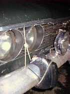
A nice feature with this tie is that it can be removed if desired while at a car show or simply placed out of sight.
The choice of cord is yours, but this happens to be nylon. It fits quite tight and will not fall out of place. Simply roll the loop up over the rubber portion as shown in photo.
The finger catch lever is a real plus for this car. It makes releasing the secondary catch much more comfortable. It is made of aluminium, bent into position and rivoted into place.
The picture of the Rover is a 1971 Rover 3500S. Originally purchased by my father, Michael Brooks, in the spring of '71. I bought this car 2 years ago, after discovering that it was still in existance approximatly 40 miles from where I live.
This car is the one that I used to get my drivers liscence when I was only 16, so it was a thrill to bring it back into the family.
This car has appx 120 k miles on the odometer. The car has had a complete restoration putting it in top condition and goes like wild. I have a Benz, and I personally feel that Rover is much nicer. In fact the Benz is for sale due to the fact I seldom drive it anymore.
Dennis Brooks
To the top
Silicon for electric antennas
The electric antennas usually get stuck after a few years. Clean t up and use silicone to grease it, then it will work better.
Tip thanks to: Ulf Ericsson
To the top
Shifting steering wheel
Shifting a steering wheel has almost never presented a problem to me. The trick I learned is as follows:
Grab the wheel at 9 and 3 o'clock. Pull hard with one hand and push hard with the other and then wriggle with stretched arms. When necessary repeat at 12 and 6 o'clock.
When the wheel was fitted to the correct torque eg. off factory, this way of removing has but once failed me when some nutter torqued down the wheel far to much which is very dangerous, it can crack the boss unnoticed and up till the days of airbags on every car I have owned I fitted a Moto Lita 14" steering wheel. (About 20 is not exaggerated). Try it. Good luck.
Lex
I couldn't believe the brute force and swearing needed to shift a steering wheel off it's splines, and I was just glad that I followed a mates advice and left the retaining nut still a few turns on to stop. Then I use a steering wheel puller or a gear puller if the steering wheel isn't equipped with bolt holes. Never been able to just pull it off.
Gavin
To the top
Rust in P6 Rovers
The following points where rust has caused problems have been noted in recent car stripping operations. Most are normally hidden from sight and require the removal of external panels to gain access for checking or fixing. With the P6 this is a relatively simple process as every panel is removable and replaceable without difficulty and without causing external paint damage if sensible care is taken.
1. Open each door and carefully check behind the door seal rubbers mounted in the body frame. Remove the stainless steel scuff plates and check under them as well.
2. Check the lower corners of front and rear windscreens. This will require the removal of the painted metal trim panels to really see what is happening. If the screen rubber is folded or crimped, water will be trapped leading to rust in the channel in the A or C pillar and can lead to rust right across the dash top if the sponge rubber air seal remains damp.
3. High up under the rear guards is a rubber seal designed to catch and retain mud/slush and gravel flung up by the wheels. I suspect that the intention is to create a block to such access to dirt and salt etc but nearly all the cars I have seen have this rubber installed with the lip curving up which creates a lovely little dam for the retention of wet dirt and other rubbish forced past the rubber by the intensity of the water and dirt velocity coming off the rear wheels. This can only be accessed after removal of the rear mudguards which is luckily a very simple job. One of my cars had holes rusted right through into the boot above the rear wheel arch so check it soon! While the rear guards are off clean all round the tail light assembly also as this is a favourite mud/slush resting spot.
4. Rear boot frame between the bumper bar and boot and around the (rear axle) top link pivots. Check this while the rear guards are off and remove the rear valance (below the boot lid) to do a thorough job. Many owners have found holes in the rear corners of their boots caused by mud/slush building up below the tail-lights and there have been instances reported of the back wheel coming loose at speed after the top link pivot has pulled out of the rusty boot side (which causes an interesting rear wheel stearing effect I believe). The extra panel at the rear of the boot inside the trim panel can become filled with mud/slush and water and rust out and as the jacking block is integral with this panel and rear of the boot this could be very expensive to repair if not corrected early.
5. Main chassis box or frame along both sides of the car. Check by removing back seats to check inside and if necessary remove front seats and carpet. To check from outside you need to remove the rocker panel which, while simple in theory, is often tedious in practice due to rust-seized screws. The inside of this box is primed with some special rust preventive paint during manufacture and there are several drain holes along its bottom edge but these can become blocked with mud/slush and then the rust starts eating away your structural strength. Well worth injecting fisholene through the holes on the inside of the frame. Check also that the little cover bungs placed into the ends of this box section in the rear wheel arch (viewable from the wheel arch and often obscured by tar paint) are still in place and effective, otherwise they should be replaced or at least re-sealed.
6. Doors. Notorious in all makes for rusting out along the lower joint. In some New Zealand fabricated cars I have observed NO PAINT WHATSOEVER inside the doors. (Note for UK & US Roverphiles: Australian cars were imported either as complete cars from England or, more often, after being fabricated in New Zealand from CKD kits exported by the factory for the purpose.)
7. Under the floor carpets. Seams around wheel arch and along floor edges were sealed in manufacture with a healthy bead of sealing goo. I have observed situations where the seal is missing, whether pulled out during repair or never put in I cannot say, and such seams leak and the heavy underfelt gets wet resulting in rusting floors. Windscreen rubbers (both front and rear) are another notorious source of leaks which trickle down behind the upholstery and dash to end up under the carpets, or in the back under the seats in that well beside the main body side beam.
8. Inside the front guards both at the front around the parking lights and at the rear where a corrugated beam stands only a few mm from the outer skin to support the lower rear of the wheel arch. Mud/slush build-up in either place leads to rapid rusting from the inside which can be prevented through regular in-situ cleaning. At the rear of the front guard is a panel attached to which is a rubber seal and dirt forces its way past this seal to accumulate along the back of the seal and cause a rusty nuisance also.
9. All P6 Rovers were undersealed with a heavy tar based goo during manufacture. This has proved remarkably good at keeping water and gravel away from the painted underneath of the floor pan. However, after thirty or more years this goo should be carefully inspected every few months to ensure it is still doing the job it was designed to do and hasn't become a trap behind which water is held. The tar can become cracked but still hang in place thus providing not only access to the steel floor but a dam holding a thin film of moisture up against the steel floor which leads to rapid rusting. Tap the tarry film with your finger to ensure it is still firmly adhering everywhere and look closely for any sign of cracks or missing bits.
If you have never done so, the idea of removing panels from your P6 may seem rather daunting. However it is relatively easy to do and may well prevent a serious rust problem. It would be very simple to remove the front & rear bumper bars, the four mudguards, all the seat squabs and floor carpets, thoroughly check all the above points, apply fisholene or other rust protection and replace everything in one afternoon, but novices should allow a day and check your service manual or obtain some experienced advice before you start.
Regards
Ian Harrison
To the top
To install a GM Delco Remy alternator in a Rover P6 2000 SC or TC
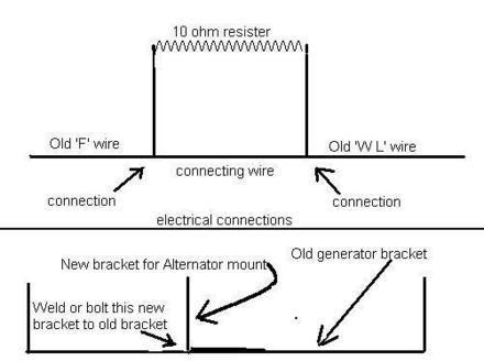
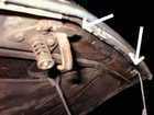
I found the best alternator to use was a 63 amp. With built in regulator. This alternator fits onto the original Rover dynamo bracket with the addition of another leg welded or bolted in the correct place to pick up the back support bracket of the alternator.
First disconnect the battery
You must make sure that you bolt the alternator to the correct side of the Rover bracket at the front so as the pulley is in line for the drive belt. You will have to go to your local wrecking yard and buy an adjusting bracket that has a curve in it as the plastic one that is fitted to your Rover will not fit the alternator it is not long enough and needs to have a curve in it.
Before installing the alternator look at the back and familiarize yourself with the electrical connections. There are three in all, a 3/16 bolt off to one side with a nut on it, this is the 12volt supply terminal, around the out side edge you will see two spade terminals recessed into the body of the alternator these are marked R = for regulator and F = for field.
Once the alternator is in place and the drive belt on and adjusted the next step is to start the wiring, first you need to supply the alternator with 12 volts, this you connect to the 12volt supply terminal, the 3/16 bolt.
On automatics you can take this feed from the hot terminal of the starter motor solenoid as it is on the same side of the engine and not far from the alternator, you should use at least a #10 wire, If you run this wire behind the engine mount leg be sure it is well insulated and will not rub on the engine mount.
On the TC the feed can still be taken from the starter solenoid, except the solenoid is not mounted on the starter motor. Make a short jumper wire long enough to Connected from the 12 volt supply terminal on the Alternator to the spade connector marked 'F' on the alternator.
At this point with only these connections made the alternator will now charge and regulate itself. But the ignition warning light will not work.So if you are not bothered about a warning light or if it is charging or not, the job is finished.
If you want the ignition warning light to work, this is what you do. Down by the new alternator you will see the two wires that you removed from the dynamo generator when you removed it.
One has a large spade connector the other a small spade connector, take the wire with the large spade connector and fold it back on itself and tape it back out of the way, now take the small spade connector and plug it in to the terminal on the back of the alternator marked 'R' = relay. Now go up to your original Lucas relay unit and unplug the spade connector marked 'F'=Field and the spade connector marked 'W L'=warning light. Now you need to join these to wires together with a 10 ohm resister in parallel.
The best way to put this lot together is by using a plastic connector block, as you must make sure that none of these connections touch the body of the car ie. ground. Do not put the resister inside the car behind the dash as it will get warm during it's operation it needs to be under the hood where it has ventilation. Having made this connection your ignition warning light will now work i.e. when you turn on the ignition the ignition warning light will come on and when you start the engine and the alternator starts to charge it will go out. If it comes on while driving it means that your alternator has stopped charging.
Barry Lafbery<
Chilliwack, British Columbia, Canada
To the top
ACR alternators on a P6
For a start all alternators require at least 2 wires to work:
* battery (B)
* warning light (WL)
Alternators with built in regulator, ACR, generally have 3 connections, but apart from very early "battery sensing" types, two of these terminals are internally connected and hence only require 2 connections to work.
Use a Lucas 38ACR or larger Lucas ACR alternator as this type of unit will accept your existing pulleys and bracket and fanbelt without problem. Note these units come in left and right handed versions, but it is possible to convert one to the other by undoing 3 screws and rotating the front casting. Connections this type and other 3 wire alternators three connections
1 15 amp lucar spade --- warning light
2 2 offf ---- 35 amp lucar spades
Connect 1 or both to the battery + terminal.
To convert a car fitted with a separate alternator control box (or a dynamo) to an ACR alternator simply mount the alternator connect together at the control box the main feed (thick brown wire) to battery, to thick wire that goes to the alternator and connect this to one of the 35amp spades. Then connect the wire (WL) that connects the control box to the dahboard warninglight, to wire what was formerly the field (F) wire and connect this to the 15 amp spade on the alternator. In addition I normally connect the remaining spade connector to battery (either at the battery terminal or the battery connection on the statter solenoid using heavy gauge wire.
Note that ACR units are very dependant on good well made connections and arcing will cause voltage spikes which will stop the alternator charging.
Thanks to:
Andy MacFadyen
To the top
Bosch alternators on a P6
I have been using a Bosch 55 amp first in a MK 1P5 and then in my various P6's.
Obtain a bottom bracket for the alternator (being in Australia I used one from a holden). Drill an extra hole in the flat plate that the dynamo bolts to (I retained the rubber washers to absorb vibration) and elongate the holes so that the pully can be alligned with the crank and water pump. Attach a straight top bracket but move the attachment point out along the bracket that supports the air cleaner neck. Use the same fan belt as before (yes NO CHANGE NEEDED).
Attach the power lead to the battery lead at the solenoid (I use 6mm wire or two strands of 5mm).
As this alternator includes a regulator all you need is an indicator on the dash so connect the two centre wires on the regulator together and connect the indicator terminal to the appropriate connector on the alternator. So simple and everything works.
I then fit relays to the lights and install decent headlights. Four x 100 watts behind italian carrello shells will find most stupid kangaroos before you hit them - they do a lot of damage to cars and trucks out here.
Thanks to:
Jim Boffey
To the top
One thread alternator?
Q: Has anyone converted a 2000 TC dynamo/generator equipped electrical system to a single wire alternator system?
A: For a start all aternators require at least 2 wires to work - battery (B) and warning light (WL) - what I think you want to fit is an alternator with built in regulator - an ACR - these generally have 3 connections but apart from very early "battery sensing" types two of these terminals are internally connected and hence only require 2 connections to work.
Use a Lucas 38ACR or larger Lucas ACR alternator as this type of unit will accept your existing pulleys and bracket and fanbelt without problem - note these units come in left and right handed versions but it is possible to convert one to the other by undoing 3 screws and rotating the front casting.
Connections this type and other 3 wire alternators three connections:
1. 15 amp lucar spade - warning light
2. 2 off - 35 amp lucar spades connect 1 or both to the battery + terminal.
To convert a car fitted with a separate alternator control box (or a dynamo) to an ACR alternator simply mount the alternator connect together at the control box the main feed (thick brown wire) to battery to thick wire that goes to the alternator and connect this to one of the 35 amp spades.
Then connect the wire (WL) that connects the control box to the dahboard warning light to wire what was formerly the field (F) wire and connect this to the 15 amp spade on the alternator.
In addition I normally connect the remaining spade connector to battery (either at the battery termminal or the battery connection on the starter solenoid using heavy gauge wire).
Note that ACR units are very dependant on good well made connections and arcing will cause voltage spikes which will stop the the alternator charging.
Thanks to Andy MacFadyen
To the top
Spare rotor arm for the V8
A little tip to help any of you with a V8 engine. If the rotor arm fails in the distributor and you have difficulty in finding a genuine rover rotor arm you can replace this with the rotor arm from a Nissan Bluebird 2.0 litre. This will be sufficiant to get you home or to go to your auto shop for a little while.
Hope this may help someone who is stuck for a while.
Tom Willis
To the top
Steering gear play
As my 2000 project nears roadworthiness, I've noticed something strange. When the steering wheel is at center, there is little free play (a couple of degrees) and the wheel moves smoothly when the front end is off the ground. However, at extreme lock one way or another, I've noticed a large amount of play in the wheel (30-45 degrees) where it doesn't feel like the wheel has anything going on on the other end. Being familiar with rack and pinion steering only (the 2000 being the first car I've driven that uses a different system) I'm worried. Is this a sign of impending doom, or is this normal? It doesn't get in the way of normal driving, just in tight parking lots. Speaking of steering and suspension, is there any hope of taking this car in for a 4-wheel alignment at a major garage chain, or is this something that only a Rover specialist would know how to do?
Tomas
This is perfectly normal. The steering gear is setup with nearly zero play in the center position. When turned to maximum lock you will get a fair amount of play. This is because of the way the steering gear internals are machined. In part this is because the greatest wear occurs in the straight-ahead position. (If you drive 600 000 miles or more you'll have steering with no play anywhere.
If you want to adjust it, jack the front wheels off the ground and then adjust the box until you have minimum play center, but no stiffness or binding when turning the wheel. It's possible to get it working really smooth this way.
To the top
SD1 gearbox in a P6B
The SD1 5 speed gearbox into an auto P6B is a good swap to do and makes a huge difference to driveability.
To the top
The Charcoal canisters
The charcoal canisters are there for escaping fumes from the carbs. They absorb the excess fuel vapors when the engine is turned off that escape from the carb(s). Ever wonder why your older cars smell up the garage with gas fumes after a drive and then sitting? That's the fuel vapors escaping from expansion of fuel going out the float vent.
Once the car is restarted, the excess fuel is then drawn back into the carbs where high idle creates a high vacuum.
The canisiters do double duty. It keeps fuel vapors from escaping into the atmosphere and helps provide a richer mixture needed when running cold. If the carbs were to flood, the canisters have a return line to the tank so they will not overflow into the atmosphere.
Actually, with no moving parts and a simple function, they are quite an ingenious item.
You can replace the charcoal in the canisters with stuff of comparable granularity [about 2mm.] obtained from a pet/hobby shop, normally sold for aquaria. Too fine and it would pack; too coarse and it would jam when poured in. Very fiddly and time consuming. You have to get the granules round the bend without going round the bend yourself!
On reflection, in future I'd drill a hole in the top or side and fit a plug for filling. I seem to recall there's a cautionary note in the workshop manual to not blast air into them. In case they explode, one presumes. They were obviously not designed to be maintained.
To the top
How to free a frozen clutch
Q
Okay, everybody
Near as I can tell, the new but dormant for several months clutch on my SD1 is stuck to the flywheel. Please contribute a variety of yarns and sage advice about freeing clutches. I don't want to hear anyone suggest that I drop the trans and do it the right way. My psyche isn't up to it, right now.
Come on, now, everybody participate . . .
Glen Wilson
A
Select a gear then tow the car slowly and drop the clutch.
Worked for me.
Rob Connolly
Start the engine and (with some help) push the car fast enough to pull the stick into second gear. You may hear the gearbox complain just a bit. Once in gear, push the clutch pedal in and accellerate and decellerate while holding the clutch in. You'll probably need a short stretch of road, but the disc should free up without much trouble.
This method has always worked for me. The flywheel and pressure plate probably just rusted a bit, and sort of "glued" themselves to the disc.
Duane Kennard
Have you thought of towing and working the clutch as you pass through the lovely Pennsylvania countryside? How about putting the car in gear, setting the brakes and barring the engine over by hand. With the engine running, set the brakes and shift into gear? Of course, you could also simply pull the engine . . .
Merle K Peirce
Frozen clutch in Denmark usually means a rusted together lump of immovable parts after a winter in the garage. Problem is easily solved though, just get the car to a straight road and run it for a couple of miles, on a high way without much traffic. The vibrations and the heat change will freee the most "frozen" clutch within a couple of minutes.
Willdo Tek
This way you avoid a frozen clutch!
If you have a manual transmission keep the clutch depressed using a wood block to hold the pedal down This will avoid the clutch plate "freezing" to the flywheel.
Patrick
To the top
How to clean brake discs
Q
After 8 years storage my rotors are rusty. What is best way of cleaning off rust to become drivable with out dissassembly and having them turned down.
A
Assuming they're not badly pitted
Unbolt and hang the front calipers
Wire brush the rust to remove the loose stuff
Spray them with brake disc cleaner
Put everything back together
The brake pads will do a good job of cleaning up the discs. For very light surface rust just drive off and let the pads clean it up.
Best way to go about it without removing the rotors is with coarse sandpaper.
Tio the top
How to fix a SD1 fuelpump
Afternoon everyone,
Just thought I'd recount a little victory over parts manufacturers that just want you to spend more money.
My fuel pump had packed in (1983 SD1 Vitesse injection) and I was looking for a replacement. Anyway, there's a really nice guy in Warrington called Hugh who seems to keep all sorts of bits for SD1s. I found his number in the Auto Trader as he wants to get rid of some bits. He thought that as it needed replacing anyway, there would be nothing to lose by pulling the thing apart and attempting to free the pump. So I did.
The pump is made by Bosch and is non user-serviceable. It consists of an aluminium cylinder with inlet at one end, and a plastic component containing outlet and +ve & -ve terminals at the other. The plastic "disc" is surrounded by a shiny chrome sleeve which holds it on to the aluminium cylinder. With a sharp screwdriver I peeled back the end of this sleeve which is crimped onto the cylinder, and then unscrewed it from the pump body. Then I pulled the plastic end out. It turned out to be the end of the pump itself, and has a rubber O seal around it (very stiff to get out). The pump is an electric motor that drives a centrifugal pump with tapered bearings in it. As the motor spins the bearings move outward in their track and squeeze the fuel out. The fuel itself passes through the motor so that the whole thing, armature, windings, bushes, magnets etc is completely submerged in fuel.
The reason it had jammed was that a small circlip had got wedged between the motor and the magnet, not that the pump had got stuck. I've no idea how the circlip got in there as there was no place obvious it had fallen off. Maybe it had been there since manufacture and just moved at the wrong time!
Anyhow, no sign of rust, everything smooth and shiny, loads of life left in the brushes, so I stuck it all back together, screwed the flange back up REALLY tight and put it back on the car.
So that's £160 saved then.
:-)
Mark Jaffrey
This fuelpump is used by many other cars. It has the Rover number 0580 464 014. The same pump on the BMW 320i 1985 has number 0580 464 013. Thanks to Fredrik Wallerius.
To the top
SD1 electrics
Q.
Prince of Darkness!
Driving home in my series I SD1 3500 last night there was a sudden electrical overheating smell inside the cabin, the alternator drive belt started screaming, the dashboard lights flickered and then went out. Pulling over I found the fuse for the side/tail and auxilliary lights had blown. I replaced it with a spare. 10 seconds later the same thing happened and the fuse blew. Having used all my spare fuses I got home driving on fog lights. Obviously I've got some sort of massive short in the circuit somewhere, but how the hell can I locate a short in this extensive circuit when it self-destructs every time I try and put current through it?
Peter
A.
Put a LIGHT BULB in where the fuse goes - then turn it on. The light bulb will glow very brightly, and the entire circuit will be "hot". now use your tester, or another light bulb and go somewhere in the middle of the suspected problem circuit and look for the conditions. when you do locate and remove the short, the light bulb will "dim down" a long way, and you can replace it with a fuse. Your most likely areas of concern are places where mechanical connection to the car frame is made. The wires can fray where they are tied together, or to the chassis. If the short was as bad as you mentioned, you will probably be able to smell the burnt wires when you get close.
Good Luck!
John D.
The wiring in the hatch (linked to the number plate lights) is a common place for shorts. If your hatch hasn't been rewired yet this is a good place to start.
Gavin W
To the top
How to fix new seats
Dennis Brooks in Canada is a professional upholsterer - and a Roverfan.
This is what Dennis says about the P6 seats:
The Rover seats are basic construction as far as the coverings are concerned. You will find that often leather seats are really only leather faced, so the replacement panel of leather is quite small. My P6B has a good quality vinyl that is still on the market today - even a good grain match.
There are only two metal fabric tension bars used on a P6 seat unit and they are no problem to fasten in place. So although it takes time to remove and refit upholstery it is not a hard process.
To the top
The Holley carburettor
Carburettor CFM=3D
Engine Engine_cid_x_Max_rpm
3456
Therefore 215_x_6000 =3D 373.2 cfm
3456
So far the 390 cfm Holley is close enough.
These figures equate to a volumetric efficiency of 100%. Since the VE of a standard Rover V8 is about 75% the Holley 390 is more than adequate. In fact ideally suited.
The Holley 4160 has a fixed metering plate equivalent to a secondary jet of .53.which is too lean.
The Holley 4150 has a secondary metering block,where you can change the jets if needed.
There are a number of variables which have to be taken into consideration, such as Single or Dual plane inlet manifolds, compression ratio, even your height above sea level.
The Holley is a very basic, simple carburettor. I wish every carb had the same facilities for fine tuning.
The settings which I have found that work well with a Rover V8 are: - Primary-.52 Secondary-.54 Power valve 7.5 Hg and .28 squirter obviously these need fine tuning according to your own applications.
From what I`ve read Hardcastle is only reading from other books not from personal experience, I might be wrong but I dont think so . . .
I have 25 years experience as a motor mechanic,specialising in rover V8`s I have owned P4,P5,P6 and 27 SD1`s including one twin turbo fuel injected SD1(very quick).
Basically a Holley is very simple but if you dont know what your doing leave it to someone who does.
And remember if it aint broke dont fix it!
Jim Allen
To the top
Hydralic tubes
Q.
I need to replace the flexible (plastic) brake line that connects to the clutch slave cylinder. It leaks at the connector. Any help?
A.
Any industrial supply store that does hydraulics can supply suitable replacement.
It's a straightforward nylon tube. Get the counterman to look for size to match the ID and wall of the existing hose away from the fitting and a pressure rating of 1200+ lbs working.
To install, remove the old tube from the metal fittings WITHOUT putting lengthwise scratches on. Clean up the metal stubs.
Mark the tubing for the length you want pushed on to the stub with a feltpen. Heat the nylon in, at most, boiling water, then push the tubing onto the stub.
Done.
The essential part is that the tubing be undersized compared to the metal stub.
Thanks to:
Vern Klukas
To the top
Excessive camwear on the 3.5 V8
This was written by a man named Jim Allen (jimallen@onlinecol.com) and seems to be an excellent and authoritative description of the cam wear problem in our stock 3.5 liter Rover V8s. It's worth reading.
Jim writes:
For about 4 years, while I worked at a Rover dealership ('87-93), we had a cam wear problem on 3.5L engines. It dated back a ways (prior to the USA intro), according to many sources, and was common on any engine with the "detox" or "low lift" cams (the NAS '87-88 3.5L had the low lift cams). To a lesser degree, the other 3.5Ls were affected as well. A lot of cams were warranteed on 3.5L Rover engines from '87 until the last of those vehicles went out of warranty.
Most engines affected
We discovered the problem while repairing a rash of intake manifold coolant leaks. The bad lobes were often readily visible. After that we started checking when the engine was down. The earliest cam failure I saw was at 1,100 miles but I have torn apart about 50 NAS 3.5L engines in my career and only a handful did not show abnormal wear.
The 3.9, 4.0, 4.2 and 4.6L engines seem immune to the problem to a large degree, due to better designs and manufacturing. In the course of doing an article on cams a few years back, I queried 8 cam manufacturers, including some in the UK, about the problem. I was told it was due to two situations; the small diameter of the cam (which leaves less surface area when the profile is ground) and poor heat treating. Lack of maintenance, internal coolant leaks or subgrade oil made the problem worse. The surface area problem was solved by using more of the material in the blank when the cam was ground and the heat treating was improved.
Check with dial indicator
As to checking, the bad lobes can be identified visually but if you don't know what to look for by experience, you will only spot it when it gets very bad. The best method with an assembled engine is via a dial indicator. You will need to remove the rocker arms to do this, as the lifters will bleed down via valve spring pressure and give inaccurate readings. You can use the pushrods to measure from. Put the cam on the center of the heel to zero the dial and then rotate the engine to the peak lift point and record the results. Test each lobe a couple of times until you can dublicate the results exactly each time. Since the hardening is little more than .010-012" thick, if the readings vary more than that, lobe to lobe, you are into the soft stuff somewhere. Also, you can compare the reading to the lift specs in the manuals. If you have a cam out, you can mike the lobes, compareing differences between the lobes or to a new cam of the same grind.
Bad timing!
As to checking timing chains, I tested the cam timing of about 30 vehicles in the course of my Rover dealership work. Any time I had the front cover off and had a few extra minutes, I checked with a degree wheel.
I was curious as to why one engine could be a rip-snorter and the next a dog. I found that only five or six of the engines I tested were at, or close enough to, the factory spec. About a third were advanced a few degrees (up to about 4 degrees- making them the rip-sporters) and the rest were retarded (the dogs) to varying amounts (up to 8 freaking degrees). Going farther, I checked to find where the errors came from and found that every cam I checked was dead on and the end result was that the timing gears were the cause. The keyways were machined incorrectly. After that, I did not trust the factory timing gear. The few (maybe two) I replaced under warranty (no, they would not replace the units for timing errors unless the engine was grossly effected), I checked for accuracy and swapped sets with the parts dept to get a good set. If the customer was buying, I installed a Cloyes True Roller set.
I know of one customer who could feel the difference, seat of the pants!
Hope this helps
Jim Allen
To the top
Wooden dashboards
Steve Feeser is a manufaturer of wooden dash kits for the Range Rover and the Land Rover Discovery. He ships approximately 2000 kits worldwide every month.
There are kits for the Range Rover from 1996 to 1999 and for the Discovery from 1997 to 1999.
The kits have 20 pieces and it matches the factory wood already in the vehicle.
You can get more information via phone 800 327-4874 or email Steve Feeser - and don't forget to tell him, you found this at the RCoS' Website!
To the top
Can I run my old Rover on unleaded fuel?
Yes probably!
To run on unleaded, most engines simply need to have the valve seats and/or the valves changed to a harder and better material. Then you prevent the so called valve seat resession. Valve seat resession is a deformation of the valve seats due to lack of lubrication the lead in the fuel provides!
I run my Rover P6b 3500 V8 with 10,5:1 compression ratio on unleaded 98 octane fuel. It runs happily on that! This summer (1998) I even took the car from Norway to Italy, and of course I went through Germany where they ONLY sell unleaded fuel. I was cruising 140 - 150 km/h, and no problems!
ALIGN="RIGHT">Eirik Aarebrot
To the top
Medlemsinloggning
Did you know
a jumbo jet uses approx. 15,000 liters of fuel to take off?
News
Uppdaterat 2009-03-27
Tata buys Land Rover and the Roverbrand
In March 2008 the heavily indebted Ford Company sold their British prestigious carmakers Jaguar and Land Rover along with the Rover Brand, the Daimler brand and the Lanchester brand.
Read moreHistory of this day
1939: PANAM begins a regular air service from the United States to Europe